
Testing a Prefabricated Floor System (™)
Prepared by: David Richardson (Director Construction Consultancy for BRE)
Approved on behalf of BRE by: Dr Angus Jack (Associate Director Construction Consultancy for BRE)
Download the report in PDF format
Executive Summary
Grants of Shoreditch have provided a prefabricated, raised access floor system that incorporates a surface finish of granite for test. The increasing use of lightweight floors that allow dynamic displacement is likely to result in similar displacements being induced in any raised access floor installed on them. The Grants raised access flooring system is therefore required to demonstrate its adequacy when used under these structural conditions. A testing programme has been devised to assess the likely performance of the finished floor in service. The programme was devised for the system as a whole and divided into three main phases;
- Deflection (load) testing
- Rolling load testing
- Durability testing
Deflection testing
The pedestal floor tested was built upon a light weight steel sub-floor comprising of simply supported steel beam sections laid on their sides. The test was designed to subject the pedestal floor to a deflection ( and consequent curvature ) to establish resistance to building related movements.
The floor was initially raised approximately 1mm to remove the propping used to support the floor assembly during construction then lowered back to the zero position. No damage was detected as a result of this. The floor was then lowered to a deflection of approx 14.3 mm which equates to a 360th of the span. This was done in 5 increments and the floor was inspected for signs of distress at each increment. No damage was detected.
After 24 hours the floor was inspected for damage then lifted back to the starting position in five increments with inspections at each increment. No damage was detected.
After a further hour the floor was lowered back to 15 mm deflection and inspected then the deflection was increased in 2 mm increments to 25 mm equivalent to a approximately a 200th of the span. No damage was detected during this process
After 24 hours the floor was again inspected for damage then lifted back to the starting datum height in increments of 5 mm. At a deflection of 5 mm a hairline crack in one of the grouted joints near the center of the span was detected. When the floor was lifted to 0 mm deflection cracks where found in a further 3 grouted joints near mid span.
Throughout the testing no damage was observed to either the pedestals, their adhesive joints or the stone tiles themselves.
Rolling load testing
This test was designed to assess the performance of the floor panels and grouted joints under a rolling load of 450 Kg applied through a hard plastic wheel 150mm diameter and 40mm wide. The load was applied along a line so as to place the maximum bending load to the panels. The length of the test traverse was 1000mm and the loaded wheel travelled at a velocity of approx 0.3 m/s. The total number of traverses for the test was 50. The traverses were performed across the shorter dimension of the panels so that two grouted joints fell along the length of the traverse.
No damage was detected from the application of the loaded wheel to the test areas. No damage to panel or grouted joints was detected from the first pass of the load.
Damage to the grouted joints was detected after 40 passes of the wheel. The surface of the grout in the joint showed cracks along the joint line at the interface with the stone tile.
At test conclusion ( 50 passes ) there was no detected damage to the stone tiles. However the surface of the grout in the joints had become detached from the material deeper in the joint and was lying loose in the joint.
The test was repeated at a second location and the results recorded. The grout again responded in a similar fashion to that seen in the first test after approximately 40 passes of the wheel.
Durability testing
Durability testing has been designed to investigate the performance of the new system particularly in relation to the affect that water may have on its dimensional stability and strength.
The durability testing indicated that deformation of the panels (without tiles) reached an average maximum of 0.399mm after prolonged exposure to moisture (35No days). Flexural strength was affected by the panels being damp. However the tests indicated that the flexural strength recovered when the panels were dried.
Contents
1. Introduction
- At the request of Grants of Shoreditch a prefabricated, raised access floor that incorporates a surface finish of granite has been tested. It is reported that the floor is to be installed in a development in London.
- The increasing use of lightweight sub-floors that allow dynamic displacement are likely to result in similar displacements being induced in the raised access floor installed on them. The Grants raised access flooring system is therefore required to demonstrate its adequacy when used under these structural conditions. A testing programme has been devised to investigate the likely performance of the finished floor in service.
- The floor system comprises a calcium sulphate panel (manufactured by Lindner) to which 15mm thick granite tiles are bonded using an adhesive in advance of installation. The panels supplied were 600mm by 1200mm and had a profiled edge to allow bonding of adjacent panels with adhesive. In service the panels are supported on steel pedestals which are glued to the sub-floor and the panels using a flexible adhesive. The final phase of installation consists of the joints being infilled with grout.
- The adequacy of the proposed raised access flooring system design needs to be assessed under loading conditions. It was considered important that testing should assess performance against deflection equating to a 360th of the span, as well as a rolling load applied through a hard plastic wheel. Even if the entire floor panel system did not fail during normal service loading, it was considered that for aesthetic considerations any cracking of the granite any significant cracking of the grout would be considered a failure.
- There is also a need to assess the durability of the system, in particular the calcium sulphate (Lindner) panels and the way in which moisture may influence their behaviour. A testing programme has been proposed using the degree of deflection (bowing) and the flexural strength of samples taken from test panels as key measures of performance
- The proposed programme of testing will therefore include an assessment of;
- Deflection (load) testing of the flooring system.
- Rolling load testing.
- Durability assessment of panels and panel + tile.
2. Description of the project
- For the deflection and rolling load test the pedestal floor tested was built upon a light weight steel sub-floor comprising of simply supported steel beam sections laid on their sides.(Figure 1.) General view of floor constructed for deflection and rolling load testing at BRE.
- The test was designed to subject the pedestal floor to a deflection ( and consequent curvature ) to establish resistance to building related movements. The floor was initially raised approx 1mm to remove the propping used to support the floor assembly during construction then lowered back to the zero position. No damage was detected as a result of this.
- The floor was to be lowered in 5 increments to a deflection equating to a 360th of the span. This was done and the floor was inspected for signs of distress at each increment.
- After 24 hours the floor was inspected for damage then lifted back to the starting position in five increments with inspections at each increment.
- After a further hour the floor was lowered back to a deflection equating to a 360th of the span and inspected, then the deflection was increased in 2 mm increments to 25 mm equivalent to a approximately a 200th of the span.
- After 24 hours the floor was again inspected for damage then lifted back to the starting datum height in increments of 5 mm.
- This test was designed to assess the performance of the floor panels and grouted joints under a rolling load of 450 Kg applied through a hard plastic wheel 150mm diameter and 40mm wide. The load was applied along a line so as to place the maximum bending load to the panels. The length of the test traverse was 1000mm and the loaded wheel travelled at a velocity of approx 0.3 m/s. The total number of traverses for the test was 50. The traverses were performed across the shorter dimension of the panels so that two grouted joints fell along the length of the traverse.
- To investigate the performance of the calcium sulphate panel on its own and the calcium sulphate panel with the stone tile on top, two methodologies of testing have been identified. It is believed that the response to moisture of the panel will be critical and testing focuses on this parameter.
- Test A
To assess the influence of moisture, five full-size panels without stone tiles and five full-sized panels with stone tiles were initially stored under water for three days before being transferred to a test rig that allowed the panel to sit above (but not be in contact with) water thereby providing 100% relative humidity (see Figure 4). At set intervals over a period of seven days measurements were taken using a bowmeter to allow an assessment as to whether any movement e.g. warping, of the panels had occurred. It was considered that by pre-soaking the panels prior to test that this was a situation unlikely to occur in service (after which any floor would be considered serviceable) and that it represented an extreme circumstance or 'accelerated' test exposure condition.(Figure 4.) General arrangement of the durability test rig. - Test B
It was considered possible that under more normal service conditions e.g. a weekend flood, that the floor panel system may have to sit above moisture for a period of time (perhaps several days). The test described in 2.5 above was repeated except panels were not pre-soaked. The panels were left on test for 35No days. -
To support the testing described in 2.5 and 2.6 a programme of flexural strength testing was also
carried out. Taking test samples cut from individual panels flexural strength testing was carried out
in the following conditions;
- Dry as supplied.
- Wet having been conditioned as Test A for 7 days.
- Dry having been conditioned as Test A for 7 days and then dried to constant mass.
General
Deflection test
Rolling load testing
Durability Assessment
3. Findings
- The floor was initially raised approximately 1mm to remove the propping used to support the floor assembly during construction then lowered back to the zero position.
No damage was detected as a result of this.
- The floor was then lowered to a deflection of approx 14.3 mm which equates to a 360th of the span. This was done in 5 increments and the floor was inspected for signs of distress at each increment.
No damage was detected.
- After 24 hours the floor was inspected for damage then lifted back to the starting position in five increments with inspections at each increment.
No damage was detected.
- After a further hour the floor was lowered back to 15 mm deflection and inspected then the deflection was increased in 2 mm increments to 25 mm equivalent to a approximately a 200th of the span.
No damage was detected during this process.
- After 24 hours the floor was again inspected for damage then lifted back to the starting datum height in increments of 5 mm.
At a deflection of 5 mm a hairline crack in one of the grouted joints near the center of the span was detected. When the floor was lifted to 0 mm deflection cracks where found in a further 3 grouted joints near mid span.
- Throughout the testing no damage was observed to either the pedestals, their adhesive joints or the stone panels themselves.
- A rolling load of 450 Kg applied through a hard plastic wheel 150mm diameter and 40mm wide. The load was applied along a line so as to place the maximum bending load to the panels. The length of the test traverse was 1000mm and the loaded wheel travelled at a velocity of approx 0.3 m/s. The total number of traverses for the test was 50. The traverses were performed across the shorter dimension of the panels so that two grouted joints fell along the length of the traverse. The results were as follows;
- No damage was detected from the application of the loaded wheel to the test areas. No damage to panel or grouted joints was detected from the first pass of the load.
- Damage to the grouted joints was detected after 40 passes of the wheel. The surface of the grout in the joint showed cracks along the joint line at the interface with the stone panel.
- At test conclusion ( 50 passes ) there was no detected damage to the stone panels. However the surface of the grout in the joints had become detached from the material deeper in the joint and was lying loose in the joint.
- The test was repeated at a second location and the results recorded. The grout again responded in a similar fashion to that seen in the first test after approximately 40 passes of the wheel.
The rolling load test was applied to the same test floor as used for the deflection test. The failures noted above cannot therefore be uniquely attributable to the rolling load test alone. The considerable deflection imposed on the floor during the deflection test could have resulted in a loss of integrity of the grout causing the failures observed during the rolling load test.
- The results of the testing may be summarised in the following table
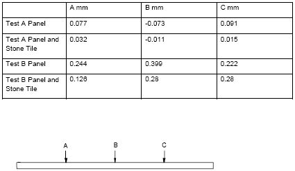
- The table presents the measured bowing of the test specimens at the locations indicated at the end of the duration of the tests. Negative values indicate that at the location indicated the panel was lifting upwards. From inspection of the results it can be seen that Test B without the stone produced the worst case of bowing producing an average maximum deflection of 0.399mm. As would be anticipated the presence of the stone reduced the extent of bowing for both tests.
- It can be concluded from the results that Test B was the most onerous test and it can be inferred that prolonged exposure to moisture (in this case 35 No days) can result in distortion of the panel flooring system in the order of 0.4mm. It would be expected that a distortion of a greater magnitude would be required to cause disruption to the floor in service.
- One of the panels with stone tiles showed slight de-bonding at a corner after completion of Test A. None of the panels exhibited de-bonding after completion of Test B.
- The results of the flexural strength testing is summarised in the following table.
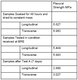
- The panels were tested without stone. It can be observed that the panels exhibit generally greater flexural strength in the transverse direction (minor axis). A considerable reduction in flexural strength is observed when panels are saturated (Test B). This reduction in flexural strength would not preclude the use of the floor for light-duty service use, such as normal foot-fall. Results of the tests conducted on the samples that were soaked for 48 hours and subsequently dried would indicate that flexural strength is regained on drying.
- It is considered that the results reported above are a worst case as the performance of the panels with stone bonded would increase the flexural strength as the panels and stone would act compositely.
Deflection testing
Rolling load test
Durability testing
Flexural Strength Testing
4. Conclusion and recommendations
- BRE has conducted deflection testing, rolling load testing and durability testing to various aspects of a prefabricated raised access floor system.
- The deflection tests indicated that the floor could be deflected to 360th of span with no damage observed to the tiles, grout, panels, pedestals or joints. The floor showed minor cracking at some of the grouted joints on recovery after the floor was deflected to 200th of the span
- The rolling load test indicated that the floor could sustain 40 passes of a 450kg load using a single wheel of 150mm diameter and 40mm wide. Beyond 40 passes the surface of the grout within the joints became detached. At test conclusion (50 passes) no damage was observed to tiles.
- The durability testing indicated that deformation of the panels (without tiles) reached an average maximum of 0.399mm after prolonged exposure to moisture (35No days). Flexural strength was affected by the panels being damp. However the tests indicated that the flexural strength recovered when the panels were dried.
Testing a Prefabricated Floor System - BRE Client report number 226-135
Commercial in confidence
Download the report in PDF format
Construction Division
BRE
Garston
WD25 9XX
T + 44 (0) 1923 664200
F + 44 (0) 1923 664096
E construction@bre.co.uk
W www.bre.co.uk
© Building Research Establishment Ltd 2005


